
Specifying Low-Backlash Planetary Gearboxes for Precision Rack and Pinion Drives: An Engineering and Sourcing Guide
Size low-backlash planetary gearboxes for rack and pinion drives: compare lost motion, bearing loads and preload, then prepare your engineering RFQ checklist.
Selection Takeaway: In a linear rack and pinion drive, the planetary gearbox's angular backlash (in arc-minutes) translates into linear lost motion proportional to the pinion pitch diameter: j_t ≈ 0.0001454 × d × j_arcmin, with d and j_t in millimeters. Ratio and nominal torque alone are insufficient for selection. Calculate tangential, radial separating, and axial forces; check bearing loads and moments at the supplier's reference datum; allocate a system error budget; and choose a preload architecture suited to the load cycle. Low gearbox backlash alone does not guarantee installed-axis accuracy.
Published and editorially checked: October 29, 2026. This global engineering and procurement guide uses SI units. Calculations are reproducible screening examples, not measured machine results or approval of a particular gearbox. Final ratings, pricing, motor adapters, and lead times require supplier confirmation against your load profile.
Scope and Engineering Boundaries: This guide covers servo-driven precision rack and pinion systems used in CNC laser and plasma cutters, large-envelope 5-axis gantry routers, automated storage and retrieval systems (AS/RS), 7th-axis robot transfer units (RTUs), and automotive body-in-white transfer lines. It focuses on precision helical and spur planetary reducers paired with ground or precision-milled racks. It excludes hydraulic linear drives, leadscrews, commercial construction hoists, and low-speed manual gate drives.
Already have your machine mass, travel stroke, and acceleration target? Submit your axis parameters for an application engineering review, or use the calculation frameworks and RFQ checklist below to audit your drive train.
1. The Core Kinematics: Converting Angular Backlash to Linear Lost Motion
The most pervasive misconception in linear drive procurement is assuming that a "1 arc-minute" or "3 arc-minute" planetary gearbox guarantees the same linear positioning accuracy regardless of the mechanical transmission attached to it.
On an ideal ball screw axis with a 10 mm lead, 1 arc-minute of gearbox output backlash corresponds to 10 / 21,600 mm ≈ 0.463 µm of lost motion, excluding screw and coupling errors. In a rack and pinion drive, the travel per gearbox output revolution instead depends on the pinion pitch diameter (d).
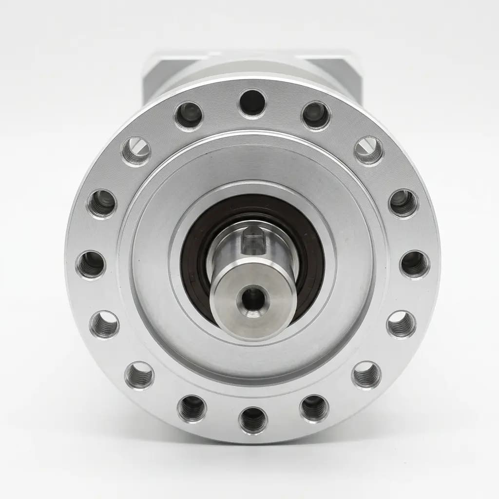
Figure 1: Illustrative gearbox output and mounting geometry. The visible keyed shaft is not evidence of an ISO 9409-1 rotating output flange or of any bearing-load rating; use the specific model's drawing and datasheet.
The Conversion Formula
Because angular backlash represents an arc of lost motion around the pitch circle of the pinion, the linear backlash (j_t) along the rack pitch line is derived from first principles:
j_t [mm] = π × d [mm] × j_arcmin / 21,600Simplifying the constant factor:
j_t ≈ 0.000145444 × d × j_arcmin [mm]Where:
j_t= Linear backlash at the rack pitch line in millimeters (mm).d= Pitch diameter of the driving pinion in millimeters (mm).j_arcmin= Torsional backlash of the planetary gearbox in arc-minutes (arcmin).21,600= Total number of arc-minutes in a full360°circle (360 × 60).
For metric calculations in micrometers (µm):
j_t (µm) ≈ 0.14544 × d_[mm] × j_arcminThe Pinion Sizing Dilemma
This mathematical relationship exposes an unavoidable engineering compromise:
-
Smaller Pinions:
- Minimizes linear lost motion for a given gearbox backlash class.
- Lowers required gearbox output torque (
T = F_t × d / 2), allowing a smaller, less expensive gearbox frame size. - Reduces mass inertia reflected to the motor for a fixed gearbox ratio; servo tuning still depends on the complete system.
- The Catch: At a fixed module, smaller pinions have fewer teeth. Check tooth-root strength, undercut or profile correction, and rack/pinion ratings. Higher rotational speed is needed for the same linear velocity, so also check input-speed and thermal limits.
-
Larger Pinions:
- Produces more linear travel per revolution, lowering pinion RPM at a given travel speed. Tooth capacity still requires a geometry- and material-specific rating.
- The Catch: A large pitch diameter directly amplifies linear backlash. A standard 5 arc-min gearbox paired with a
120 mmpinion generates nearly90 µmof linear lost motion—before accounting for rack manufacturing tolerances, tooth deflection, or thermal expansion. Furthermore, output torque demand scales linearly withd, necessitating a substantially larger, more costly gearbox.
Kinematic Translation Matrix: Pinion Pitch Diameter vs. Gearbox Backlash
The following calculated table shows the gearbox contribution only. Module is transverse module (m_t), so d = m_t z; for helical gears specified by normal module, use d = m_n z / cos beta. Application labels are illustrations, not load-capacity recommendations.
Transverse Module (m_t) | Teeth (z) | Pitch Diameter d (mm) | Gearbox Backlash: 1 arc-min (j_t) | Gearbox Backlash: 3 arc-min (j_t) | Gearbox Backlash: 5 arc-min (j_t) | Gearbox Backlash: 8 arc-min (j_t) | Illustrative Application |
|---|---|---|---|---|---|---|---|
| M2 | 16 | 32.0 mm | 4.65 µm | 13.96 µm | 23.27 µm | 37.23 µm | Compact 3D dispensing, light laser marking |
| M2 | 20 | 40.0 mm | 5.82 µm | 17.45 µm | 29.09 µm | 46.54 µm | Precision sheet metal fiber laser cutting (X/Y) |
| M2.5 | 20 | 50.0 mm | 7.27 µm | 21.82 µm | 36.36 µm | 58.18 µm | High-speed pick-and-place linear gantries |
| M3 | 20 | 60.0 mm | 8.73 µm | 26.18 µm | 43.63 µm | 69.81 µm | Standard CNC woodworking routers, waterjet tables |
| M3 | 25 | 75.0 mm | 10.91 µm | 32.72 µm | 54.54 µm | 87.27 µm | 7th-axis robot transfer tracks |
| M4 | 20 | 80.0 mm | 11.64 µm | 34.91 µm | 58.18 µm | 93.08 µm | Heavy CNC plasma / oxy-fuel cutting gantries |
| M4 | 25 | 100.0 mm | 14.54 µm | 43.63 µm | 72.72 µm | 116.36 µm | Heavy robotic transfer units (RTUs) |
| M5 | 24 | 120.0 mm | 17.45 µm | 52.36 µm | 87.27 µm | 139.63 µm | Heavy machine tool bed drives, aerospace skin mills |
2. Overhung Radial Loads and Tilting Moments: Checking Bearing Capacity
In pure rotary applications, such as driving a hollow rotary indexer or an inline ball screw via a flexible coupling, the planetary gearbox output shaft experiences almost pure torsion.
In a rack and pinion drive, the gearbox output bearings must also withstand reaction forces at the tooth mesh. Selecting only by rated output torque (T_2 N) can overlook bearing fatigue, deflection, and mesh alignment. Service life cannot be inferred without the bearing arrangement, load spectrum, speed, lubrication, and mounting geometry.
The Force Triad in Helical Gearing
For the example below, assume helical gearing with helix angle beta = 19.5283° and normal pressure angle alpha_n = 20°. These are example geometry inputs, not universal values. Helical teeth can increase overlap, but actual contact ratio depends on tooth geometry and face width. The mesh forces resolve into three components (use torque in Nm and diameter in meters for force in N):
-
Tangential Force (
F_t): The primary linear driving (feed) force required to accelerate the gantry, overcome friction, and resist cutting forces:F_t = (2 × T_gearbox) / (d) -
Radial Separating Force (
F_r): The force pushing the pinion directly away from the rack, attempting to force the gears out of mesh:F_r = F_t × (tan alpha_n) / (cos beta) = F_t × (tan 20°) / (cos 19.5283°) ≈ 0.386 × F_t -
Axial Thrust Force (
F_a): The thrust force generated by the helical tooth angle parallel to the gearbox output shaft:F_a = F_t × tan beta = F_t × tan 19.5283° ≈ 0.355 × F_t
Calculating Total Radial Load and Tilting Moment
The combined radial force acting at the center of the pinion face width is:
F_rad = sqrt(F_t^2 + F_r^2) = sqrt(F_t^2 + (0.386 × F_t)^2) ≈ 1.072 × F_tFor this example geometry, the resultant radial bearing load is about 7.2% greater than the tangential axis force, before shock and other external loads.
For an overhang (L) measured from the supplier's bearing-load datum to the pinion face-width center, a conservative magnitude bound for the bending moment is:
M_k,bound = (F_rad × L) + (F_a × (d) / (2))This scalar sum is a screening bound, not the exact vector resultant. Force directions, helix hand, and rotation determine the actual moment. Use meters for both lever arms to obtain Nm. Ask the supplier to assess radial force, axial force, and moment together at its specified datum; independent catalog maxima may not be simultaneously permissible.
Where:
L= Overhang distance from the front bearing reference line to the centerline of the pinion.d/2= Pitch radius of the pinion, acting as the moment arm for the axial thrust force.
Comparing Shaft and Flange Outputs
A shaft-mounted pinion can be suitable if the shaft, connection, bearings, and overhang are rated for the actual reversing loads. Keyed, clamped, and shrink-disc joints have different assembly and fatigue requirements. Neither shaft size nor nominal torque establishes acceptable deflection.
A rotating output flange can shorten the load lever arm, but the benefit depends on the complete pinion and bearing geometry. ISO 9409-1 describes interface dimensions; it does not certify bearing capacity, stiffness, or suitability for a rack axis. Compare the supplier's combined-load limits and deflection data, including any externally supported pinion option. See the flange versus shaft output selection guide.
3. Preload Architectures: Controlling Reversal Clearance
A gearbox specified at 1 to 3arc-minutes contributes about 9 to 26 µm of lost motion through a 60 mm pinion. Rack mesh clearance, joint movement, and elastic deflection add separate effects. Decide whether the requirement is unidirectional repeatability, bidirectional repeatability, or absolute positioning accuracy before selecting preload.
Architecture A: Single Pinion with Eccentric Mounting Flange
An eccentric flange or adjustable bracket sets rack-to-pinion center distance. This is a compact arrangement with one motor, drive, and gearbox. Set clearance using the rack supplier's mounting procedure and check the entire stroke, including rack joints. Mesh adjustment cannot remove internal gearbox backlash. Forcing the mesh tight can cause binding where alignment or pitch varies.
Architecture B: Mechanical Split-Pinion (Spring Preload)
Two coaxial pinion halves contact opposing rack flanks under spring preload. This can reduce rack-mesh reversal clearance while the load remains within the preload mechanism's working range. It does not remove upstream gearbox backlash or elastic deflection. Available thrust, spring travel, tooth loading, and lubrication requirements must come from the specific assembly's rating; there is no universal percentage derating.
Architecture C: Dual-Motor Electronic Preload
Two independently driven pinions can apply opposing bias torque to maintain contact on opposite rack flanks during reversals. The controller may adjust bias during the cycle, depending on its supported control strategy. Size each motor, gearbox, bearing set, and pinion for its own load, including circulating preload torque and heating. Load sharing, tuning, and fault response require commissioning; two drives do not automatically double usable axis capacity or guarantee zero positioning error.
Preload Architecture Comparison Matrix
| Selection Issue | Single Adjustable Pinion | Mechanical Split-Pinion | Dual-Motor Electronic Preload |
|---|---|---|---|
| Clearance addressed | Sets rack-mesh clearance | Preloads opposing rack flanks | Biases two drive paths against opposing flanks |
| Gearbox backlash | Remains in the drive path | Remains upstream of the split pinion | Effect depends on maintained opposing torque and control |
| Motor and gearbox count | One of each | One of each | Two of each |
| Usable thrust | Verify tooth and drive ratings | Obtain preload-specific rating | Check each path and controller load sharing |
| Travel constraint | Alignment and rack joints | Alignment, joints, and preload travel | Alignment, joints, cabling, and controller support |
| Cost drivers | Adjustable mount and one drive | Split assembly and maintenance | Second drive path and commissioning |
| Wear and heating | Depend on clearance and lubrication | Additional preload contact | Depend on bias torque and duty cycle |
| Acceptance test | Measure reversals along full stroke | Measure under both load directions | Measure reversals, synchronization, and fault behavior |
ATLANTA's system overview separates rack pitch error from minimum rack-and-pinion backlash and makes alignment a condition of its backlash figures. Treat any supplier's “zero backlash” claim as a defined mesh or drive condition, never a guarantee of zero total axis error.
4. System Tolerance Budgeting: Gearbox Backlash and Rack Quality
Purchasing an ultra-low-backlash gearbox while leaving rack pitch error, structural compliance, or temperature uncontrolled can spend money without meeting the machine requirement. Keep accuracy, repeatability, and reversal lost motion separate: an axis may repeat closely at one point while having substantial position error elsewhere.
For an initial worst-case magnitude budget, use:
E_screen = |j_gearbox,linear| + |j_mesh| + |F_p,rack| + |delta_load| + |Delta_thermal|This is an allocation method, not a statistical prediction or a complete servo error model. Define travel length, temperature, load, direction, feedback location, and whether compensation is active. Add control, installation, and joint errors where relevant. Do not use root-sum-square aggregation unless independence and distributions are justified.
Understanding Supplier Rack Quality Grades
Rack catalogs use quality labels such as DIN Q5 through Q10. The label alone does not specify a universal micrometer-per-meter limit, heat treatment, or installed repeatability. Request the applicable standard and edition, inspected features, measuring length, actual cumulative pitch-deviation limit, and inspection certificate. Do not assume DIN and ISO grade numbers are interchangeable.
For a concrete catalog example, ATLANTA's system overview lists DIN 3–6 racks with pitch errors below 0.012–0.036 mm per meter, and a DIN 8 system with a limit below 0.100 mm per meter. These are that supplier's listed system ranges, not universal grade definitions or promises for another rack. Its catalog download index identifies individual rack series, split pinions, and flange pinions for model-specific follow-up.
The “Mismatched Axis” Sourcing Pitfall
Consider a hypothetical 6-meter axis with a 60 mm pinion and a 1arc-minute gearbox: the calculated gearbox contribution is 8.73 µm. Assume, separately, that the purchased rack has a contractual pitch-error allowance of 80 µm per meter. A conservative six-segment same-sign stack is 480 µm, before rack-joint and installation errors. This is a screening assumption, not a prediction that real rack error grows linearly over the full stroke. Ask for full-length inspection or mapping. Reducing gearbox backlash alone does not remove that rack-error allowance.
System Matching Worksheet
| Requirement | Calculation or Supplier Input | Procurement Decision |
|---|---|---|
| Gearbox reversal contribution | Convert arc-minutes using actual pinion pitch diameter | Allocate only part of the linear reversal budget to the gearbox |
| Rack-mesh clearance | Mounted clearance across the entire stroke | Choose adjustment or preload with a stated acceptance test |
| Rack pitch deviation | Certificate, measuring length, and joint allowances | Specify numerical limits alongside the quality designation |
| Loaded deflection | Tooth, joint, shaft, bearing, and frame compliance | Request stiffness data at representative working loads |
| Thermal drift | Rack and frame temperatures, lengths, and expansion coefficients | Set operating-temperature limits and compensation requirements |
| Feedback and compensation | Encoder location, calibration, and control error | Verify installed accuracy separately from component backlash |
| Final acceptance | Both directions, several positions, defined load and temperature | Agree the measurement method and pass limits before ordering |
5. Worked Sizing Example: 7th-Axis Robot Transfer Unit (RTU)
This hypothetical 7th-axis robot transfer unit (RTU) illustrates the arithmetic, not a measured customer installation. Assume horizontal travel, one drive pinion, constant acceleration, and no process load. Robot-arm reaction loads, cable drag, emergency stops, rotating inertias, transmission losses, and design margins remain to be added for final selection.
Application Parameters
- Total Moving Mass (
m):1,600 kg(includes a 6-axis articulated robot arm, end-of-arm tooling, cables, and carriage plate). - Travel Stroke:
15.0 meters. - Target Velocity (
v_max):2.0 m/s. - Acceleration Time (
t_acc):0.5 seconds(Accelerationa = v_max / t_acc = 4.0 m/s^2 ≈ 0.41 g). - Guide Friction Coefficient (
µ):0.005(preloaded linear profile ball guides). - Selected Gearing: Helical Rack and Pinion, Module 3 (
m_n = 3), Helix Anglebeta = 19.5283°, Number of Teethz = 25. - Pitch Diameter (
d):d = (m_n × z) / (cos beta) = (3 × 25) / (cos 19.5283°) = (75) / (0.94248) ≈ 79.58 mm ≈ 0.07958 m - Pitch Radius (
r):d / 2 = 0.03979 m.
Step 1: Calculate Linear Dynamic Forces
- Acceleration Force (
F_acc):F_acc = m × a = 1,600 kg × 4.0 m/s^2 = 6,400 N - Friction Force (
F_fric):F_fric = m × g × µ = 1,600 kg × 9.81 m/s^2 × 0.005 = 78.5 N - Peak Tangential Feed Force (
F_t_peak):F_t_peak = F_acc + F_fric = 6,400 N + 78.5 N ≈ 6,479 N
Step 2: Determine Peak Torque at the Pinion
T_pinion_peak = F_t_peak × r = 6,479 N × 0.03979 m ≈ 257.8 NmStep 3: Compute Multi-Axis Forces on Gearbox Output Bearings
- Radial Separating Force (
F_r):F_r = F_t_peak × (tan 20°) / (cos 19.5283°) = 6,479 × 0.3862 ≈ 2,502 N - Axial Thrust Force (
F_a):F_a = F_t_peak × tan 19.5283° = 6,479 × 0.3547 ≈ 2,298 N - Combined Radial Load (
F_rad):F_rad = sqrt(F_t_peak^2 + F_r^2) = sqrt(6,479^2 + 2,502^2) ≈ 6,946 N - Moment Screening Bound: Assume the pinion center plane is
L = 25 mm = 0.025 mfrom the supplier's bearing datum:M_k,bound = (F_rad × L) + (F_a × (d) / (2)) = (6,946 × 0.025) + (2,298 × 0.03979) = 173.65 + 91.44 ≈ 265.1 Nm
Engineering observation: At an assumed overhang of L = 75 mm, the radial moment term triples to 520.95 Nm and the scalar bound becomes 612.4 Nm. Neither value establishes pass or fail without a specific bearing arrangement and combined-load rating. Evaluate actual force directions and both travel directions before approval.
Step 4: Gearbox Ratio & Inertia Matching
The linear travel per revolution of the pinion is:
S_rev = π × d = π × 0.07958 m ≈ 0.250 m/revAt maximum speed (v_max = 2.0 m/s), the pinion rotates at:
n_pinion = (2.0 m/s) / (0.250 m/rev) = 8.0 rev/s = 480 RPMRatios of i = 5:1 and i = 7:1 require input speeds of 2,400 and 3,360 RPM respectively. A 3,000 RPM nominal motor does not automatically support continuous operation at 3,360 RPM. Check the motor torque-speed curve and the gearbox's continuous, peak, and thermal speed limits; see the thermal and duty-cycle sizing guide.
The reflected mass moment of inertia at the gearbox input is:
J_load_reflected = (m × r^2) / (i^2) = (1,600 kg × (0.03979 m)^2) / (7^2) = (1,600 × 0.001583) / (49) ≈ 0.0517 kg × m^2If a candidate motor has an assumed rotor inertia of J_motor = 0.0085 kg × m^2, the mass-only inertia ratio is:
(J_load) / (J_motor) ≈ (0.0517) / (0.0085) ≈ 6.08:1The resulting 6.08:1 ratio is only an input to servo selection. Include gearbox, pinion, coupling, and other rotating inertias and follow the drive supplier's tuning guidance. It does not prove stability or sufficient motor torque.
Step 5: Check Power, Torque Duration, and Duty Cycle
Just before acceleration ends, the ideal mechanical output power is 6,479 N × 2 m/s = 12.96 kW. At 7:1, ideal motor torque is 257.8 / 7 = 36.8 Nm at 3,360 RPM, before losses and rotating-inertia torque. A 3.5 kW continuous motor rating alone therefore cannot approve this move; the motor and drive must support the required peak torque, speed, and duration.
For a defined piecewise-constant cycle, calculate T_RMS = sqrt(sum(T_k² × t_k) / sum(t_k)), including acceleration, braking, dwell, and preload. Compare this with the applicable continuous thermal rating, and check peak and emergency-stop limits separately. Confirm the gearbox supplier's own equivalent-load and bearing-life method rather than substituting RMS torque for every rating.
6. Sourcing & Engineering Checklist: Preparing the RFQ
When purchasing low-backlash planetary gearboxes for rack and pinion axes, specifying only motor flange size and ratio leaves load capacity and installed performance unresolved. Use this 10-point technical checklist to validate your parameters before requesting a formal quotation:
- 1. Complete Dynamic Force Profile: Have you calculated both the continuous thermal feed force (
F_c) and the peak acceleration force (F_acc), rather than relying solely on static friction? - 2. Pinion Pitch Diameter (
d) and Module (m): Have you documented the exact module, number of teeth (z), pressure angle (alpha_n), helix angle (beta), and pitch diameter? - 3. Output Mounting Geometry: Have you specified shaft or rotating-flange dimensions, pinion center plane, and overhang (
L) from the supplier's bearing datum, and checked the joint's reversing-load capacity? - 4. Overhung Tilting Moment (
M_k): Has the supplier verified that the output bearing arrangement can sustain simultaneous radial and axial forces and the actual moment throughout the load cycle? - 5. System Backlash Budget (
j_tinµm): Have you allocated a gearbox-only lost-motion allowance, then converted it withj_t ≈ 0.1454 × d × j_arcmin, withdin mm, while budgeting mesh clearance and compliance separately? - 6. Rack Quality and Inspection: Does the RFQ state numerical pitch-deviation limits, measuring length, applicable standard/edition, rack-joint allowances, and installed acceptance criteria alongside the quality grade?
- 7. Preload Architecture Definition: Does the axis require a single pinion with eccentric adjustment, a mechanical split-pinion, or a dual-motor master-slave electronic preload system?
- 8. Duty Cycle and Thermal Rating: Have you supplied the complete speed/torque/time cycle, reversal frequency, emergency stops, preload, and ambient temperature, then checked motor torque-speed and gearbox thermal limits?
- 9. Lubrication and Environment: Are gearbox service intervals and exposed rack-mesh lubrication specified separately, with compatible lubricant, contamination controls, and any food-grade or washdown requirements?
- 10. Second-Sourcing Interchangeability: Have you compared pilot, bolt circle, shaft/flange, motor adapter, body envelope, backlash, stiffness, and combined-load limits on drawings and datasheets rather than assuming interchangeability?
Use the second-source comparison guide for replacement reviews, then send the completed RFQ checklist with your load cycle so candidate units can be assessed against the same conditions.
7. Frequently Asked Questions (FAQ)
Can I eliminate rack and pinion backlash by simply pushing the pinion deeper into the rack?
No. Adjust center distance only within the rack and pinion supplier's mounting limits. Excessive engagement can cause interference, binding, heat, and wear. Check clearance over the full stroke and at joints. Split-pinion or electronic preload can reduce reversal clearance under specified loads, but neither guarantees zero total positioning error.
Why is helical rack and pinion preferred over straight spur gearing in precision machinery?
Helical teeth engage progressively and can increase overlap, improving smoothness when geometry, alignment, and lubrication are appropriate. They also generate axial thrust and require matching helix hand, pressure angle, and module. Noise, capacity, and efficiency benefits are model-specific; they cannot be assigned a universal dBA or percentage improvement. The helical versus spur gearbox guide discusses gearbox tooth-form trade-offs separately from rack-mesh selection.
What is the advantage of an ISO 9409-1 flange over a shrink-disc shaft connection for pinions?
A rotating flange can place the pinion closer to the supporting bearings, reducing overhang. The actual advantage depends on both assemblies' dimensions and bearing datums. ISO 9409-1 interface dimensions do not establish bearing preload, load capacity, or stiffness. Compare complete drawings and ratings rather than assuming a fixed improvement over a shrink-disc connection.
How does thermal expansion affect rack and pinion accuracy over long travel lengths?
For an illustrative steel rack, assume a linear thermal expansion coefficient of alpha = 11.5 µm / (m × °C). On a 20-meter gantry, a seasonal temperature shift of 15°C (27°F) gives the following free-expansion estimate:
Delta L = 20 m × 15°C × 11.5 µm/m/°C = 3.45 mmThis is free thermal expansion using an assumed steel coefficient; actual axis error also depends on frame expansion, restraint, temperature gradients, feedback, and compensation. Lower gearbox backlash alone does not correct thermal drift. A linear encoder is one possible feedback measure, but its own thermal behavior and installation still need evaluation.
How often should a preloaded rack and pinion drive be lubricated?
Follow the rack and pinion assembly supplier's lubricant, delivery method, quantity, and interval for the actual speed, load, preload, and environment. Automatic lubrication can be appropriate for continuous-duty or difficult-to-access axes, but there is no universal mandatory method or grease grade. Gearbox fill does not lubricate the exposed rack mesh. Inspect delivery and tooth condition, and use the relevant operating manual from the manufacturer's catalog and manual index.
When is a right-angle planetary gearbox preferred over an inline planetary gearbox for rack drives?
A right-angle unit can help when motor clearance or guarding prevents an inline installation. The right-angle stage type depends on the product. Compare its efficiency, added backlash, thermal rating, mounting options, and output bearing limits against an inline unit for the same load cycle.
8. Primary Sources & Engineering References
Checked October 29, 2026. These three URLs are primary manufacturer resources from one supplier, not independent comparative testing. Catalog figures are specific to the listed products. The formulas and hypothetical RTU calculations above are analytical screening work; they do not report measured hardware performance.
- ATLANTA Drive Systems — manufacturer website: Identifies the supplier and provides access to its rack-and-pinion product and support resources. This company homepage is not a technical handbook or evidence for a particular performance rating.
- ATLANTA — Rack & Pinion Drive Systems: System-level examples of rack grades, pitch-error ranges, mesh backlash, and the dependence of backlash on alignment. Do not generalize these figures to another supplier's rack or to installed-axis accuracy.
- ATLANTA — PDF Catalog Files: Download index for rack selection and ratings, split pinions, ISO 9409-1 flange pinions, lubrication, and operating manuals. Obtain the current document for the exact part number before approval; the index alone does not verify bearing life or dynamic performance.
Need Application Engineering Support for Your Linear Axis?
Sizing a low-backlash planetary gearbox for a demanding rack and pinion axis requires balancing kinematic backlash, dynamic feed forces, bearing tilting rigidity, and total BOM cost. Over-specifying wastefully inflates production budgets, while under-specifying risks catastrophic field failures and costly machine downtime.
Contact our engineering team with your axis parameters to request a candidate gearbox review. Include the completed RFQ checklist, pinion drawing, load cycle, positioning requirement, and motor torque-speed data. Ask for model-specific CAD, combined-load limits, lubrication instructions, and a quotation with confirmed scope and lead time before ordering.
Author

More Posts
Specifying Low Backlash Gearboxes for AGV and AMR Wheel Drives
Choose low backlash gearboxes for AGV/AMR wheel drives with a 2026 checklist for radial loads, shock ratings, bearings, backlash, and RFQ review steps.

Decoding Planetary Gearbox Accuracy: True Backlash vs. Lost Motion
Stop sizing high-precision axes based on a single backlash number. Learn how to read hysteresis curves and calculate real-world lost motion before your machine fails in the field.
Flange Output vs. Shaft Output Planetary Gearboxes: A Sourcing and Engineering Guide
Compare flange output and shaft output planetary gearboxes. Learn when to pay the premium for flange mounts based on torsional stiffness, space, and BOM costs.